Product Introduction
The automatic water cut-off device for oil tanks is a new-generation product independently developed and designed by Honghu Tianxin Petrochemical Equipment Manufacturing Co., Ltd. in response to the current needs of de-watering in the petrochemical industry. It is made of stainless steel (carbon steel) and features a reasonable design, simple structure, large drainage capacity, fast oil return speed, strong corrosion resistance, and convenient, safe and reliable operation. This product is used in the petroleum and chemical industries, replacing the manual water cutting method for oil tanks and achieving automatic water cutting. It significantly reduces the labor intensity of operation and the hydrogen sulfide poisoning phenomenon that occurs during manual water cutting, and also reduces oil waste and environmental pollution. At the same time, it meets the regulatory requirements of the petrochemical system for the drainage to be channelized and pipelined.
The development and application of the automatic water-cutting device for oil tanks undoubtedly makes an important contribution to the improvement of production technology and automation in the petrochemical industry. It solves the problem in the petrochemical industry where oil tank dehydration is carried out through manual operation, where the separation of oil and water cannot be strictly controlled, and the drainage contains a relatively high amount of oil, resulting in waste of oil products and environmental pollution; it also overcomes the significant safety hazards caused by human error operations.
The automatic water cut-off device for oil tanks is installed at the bottom of the oil tank. It utilizes the mechanical force generated by buoyancy to automatically start the drainage process. Once the drainage is completed, it can automatically shut off without the need for manual intervention. It does not consume energy and does not have explosion-proof issues. It not only ensures the safe operation of production but also reduces the labor intensity of workers and the pollution to the environment. It has a wide range of applications, is easy to install and use, has good safety performance and high reliability.
Function and Usage
Function: Installed on the drain pipe or sewage pipe at the lower part of the oil storage tank, it automatically opens to drain water and automatically closes after the drainage is completed.
Usage: Suitable for automatic oil collection and drainage of oil tanks in production facilities and oil storage areas in the petroleum and petrochemical industries.
Product Technical Characteristics
1.It perfectly applies Archimedes' principle and the amplification principle of the lever, ingeniously converting the buoyancy difference caused by the density difference of oil and water into power, thus achieving automatic water cutting without the need for energy.
2. After oil and water enter the water separator, they can be automatically separated. The remaining oil can quickly flow back to the oil tank. When the water level in the water separator reaches a certain height, the valve core opens to drain the water, and when the water level drops to a certain level, the valve core automatically closes.
3. After the water cutting process is completed, a certain height of water level is maintained in the water cutter, forming an automatic water seal; the dehydration valve undergoes two sealing operations to ensure no oil leakage.
4. This product uses a non-backpressure non-pressure valve. The lever first drives the needle valve to move, causing the internal and external pressures of the valve core to be equal. The lever continues to move, and the needle valve and the valve core start cutting the water together very flexibly. During the oil inflow and outflow of the large tank, normal water cutting can be achieved.
5. The counterweight is fixedly installed inside the float. When the density of the oil changes, there is no need to adjust the counterweight again.
6. At the bottom of the water-cutting device, there is a drain valve. Cleaning the water-cutting device does not require disassembling it. It only takes ten minutes to complete the cleaning of one water-cutting device.
7. The drainage outlet of the water cutter can be placed in any position around, and there are 360° drainage directions to choose from.
8. Small in size, it is highly adaptable to storage tanks with relatively low tank bottom foundations.
9. Customized according to the specific requirements of the users, meeting the water-cutting requirements under different working conditions.
Technical Specifications
1.Work pressure < 0.2 MPa
2. Working temperature: 0 - 80℃
3. Water cut and oil content: ≤ 80 ppm
4.Applicable medium density: p ≤ 960 kg/m³
5. Steam pressure: 0.1 MPa to 1.0 MPa
6. Application scope: Suitable for liquid separation of oil products with different densities and other chemical products.
7. Nominal Water Drainage Capacity:5 Cubic metres per hour、10 Cubic metres per hour、15 Cubic metres per hour、20 Cubic metres per hour、30 Cubic metres per hour、60 Cubic metres per hour
Working Principle
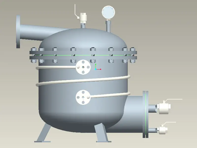
This product consists of a cylinder body, inlet and outlet water valves, and an automatic control device (refer to Figure 1). By utilizing the density difference between different oil products and water to generate buoyancy and employing the lever principle, the buoyancy difference of the float in the oil-water medium causes the float to move up and down. Through a highly sensitive lever system, the obtained buoyancy difference is amplified by a factor, making the valve opening and closing more sensitive. It can also be automatically monitored according to the user's needs, enabling the automation of the dehydration management in the tank area.
An inlet is provided at the upper part of the water cut-off cylinder, and a drain outlet is set at the lower part. There is a float ball inside, which is connected to another small valve core through a connecting rod. The counterweight is installed on the upper part of the float ball via the connecting rod. When the float ball is lifted or lowered due to the buoyancy, it will drive the valve core to open or close the drain outlet through the connecting rod.
Product Structure Diagram
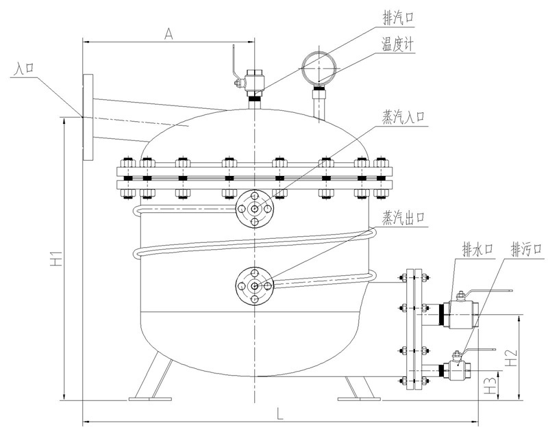
Specifications and Technical Parameters
Model | H1(mm) | H2(mm) | H3(mm) | A(mm) | L(mm) | Inlet (mm) | Outlet (mm) | Ball Valve for Sewage Outlet |
HQS-5 | 560 | 160 | 50 | 375 | 760 | DN80 | DN25 | DN32 |
HQS-10 | 660 | 175 | 60 | 400 | 810 | DN100 | DN32 | DN40 |
HQS-15 | 700 | 180 | 60 | 400 | 820 | DN100 | DN40 | DN40 |
HQS-20 | 780 | 190 | 70 | 400 | 820 | DN100 | DN40 | DN40 |
HQS-30 | 880 | 210 | 80 | 450 | 910 | DN100 | DN50 | DN40 |
HQS-60 | 1100 | 245 | 110 | 500 | 1030 | DN100 | DN65 | DN40 |
Installation Diagram
Installation Instructions
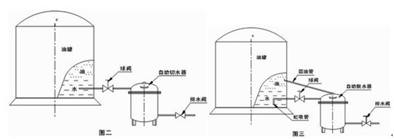
1. This product is required to be installed on a stable and solid foundation. The inlet should be parallel to or slightly lower than the drainage outlet of the oil tank.
2. The installation methods are two types: ① Installation of oil tanks without a siphon pipe (refer to Figure 2). ② Installation of oil tanks with a siphon pipe (refer to Figure 3).
3. All fasteners in the pipeline should be tightened, and the connection points should be sealed. No liquid leakage is allowed.
4. The valve connecting the oil tank and the dehydrator should be a gate valve or other straight-through valves with no bends, otherwise it will affect the return of oil.
5. In northern regions, steam heating pipes should be installed to prevent freezing. The connecting valve of the cut water device with the steam heating pipe and the oil tank is not allowed to be closed to prevent over-temperature and pressure increase.
Important Notes
1. Valves at the outlet of the oil tank should be preferably of the straight-through ball valve type.
2. The pipeline from the oil tank to the water separator should be horizontal or sloping towards the water separator.
3. For the oil tank outlet pipe with a bent pipe type (siphon type), it is recommended to remove the bend. If the bend cannot be removed, an oil return pipe must be set up, with a pipe diameter of DN32.
4. In cold regions or for thick oil products, a "stand-alone temperature control valve" should be installed for water cut-off.
5. In cold regions, it is recommended to add heating and insulation to the oil tank cut-off pipeline and oil return pipeline.
6. For large-capacity oil tanks or those with a high water content in the oil, or for oil tanks with a short cutwater cycle, it is recommended to increase the number of cutwater devices appropriately.
7. Regularly remove the sediment in the cutwater and filter to ensure the normal operation of the cutwater.
8. Regularly check if the cutwater is leaking oil and replace the sealing ring of the double valve in time.
9. During the operation of the cutwater, pay attention to exhaust to avoid air blockage that may affect the normal operation of the cutwater.
10. It is a normal phenomenon if the water separator fails to cut off the emulsified oil sludge layer properly. A manual water cut-off port should be set up before the water separator.
Fault Resolution
Sequence Number | Fault | Causes of Fault | Handling Method |
1 | After installation, the water cutter fails to cut water. | 1. The relevant valves are not opened. 2. The temperature is insufficient and the medium solidifies. 3. There is air pressure inside the water cutter. | 1. Identify the cause and open the relevant valves. 2. Appropriately increase the steam temperature. 3. Open the exhaust plug to remove the air. |
2 | After the water cutting process, there is still a small amount of water flowing out with oil droplets. | 1. There are foreign objects stuck inside the water cutter. 2. There is too much sediment inside the water cutter. | 1. Remove the foreign objects. 2. Clean the water cutter. |
3 | Leakage occurs at the sealing outlet of the tank flange. | 1. The sealing gasket is deformed. 2. The tightening force of the bolts is uneven. | 1. Replace the sealing gasket. 2. Re-tighten the bolts evenly. |
4 | Contamination with oil during water cutting | 1. The oil has an emulsification phenomenon 2. The oil density is too high | 1. Allow the emulsified oil to fully separate in the tank 2. Appropriately adjust the weight distribution |